This lab is a extenstion of the previous lab, we will combine all the examples we show in the previous lab to form a dataloader.
This dataloader can capture IMU data, temperature data, timestamp associate with the data being displayed. The data can be capture in 2 ways. First, it will by default display data on the serial monitor on Arduino IDE. Second, we can store those data to SD card.
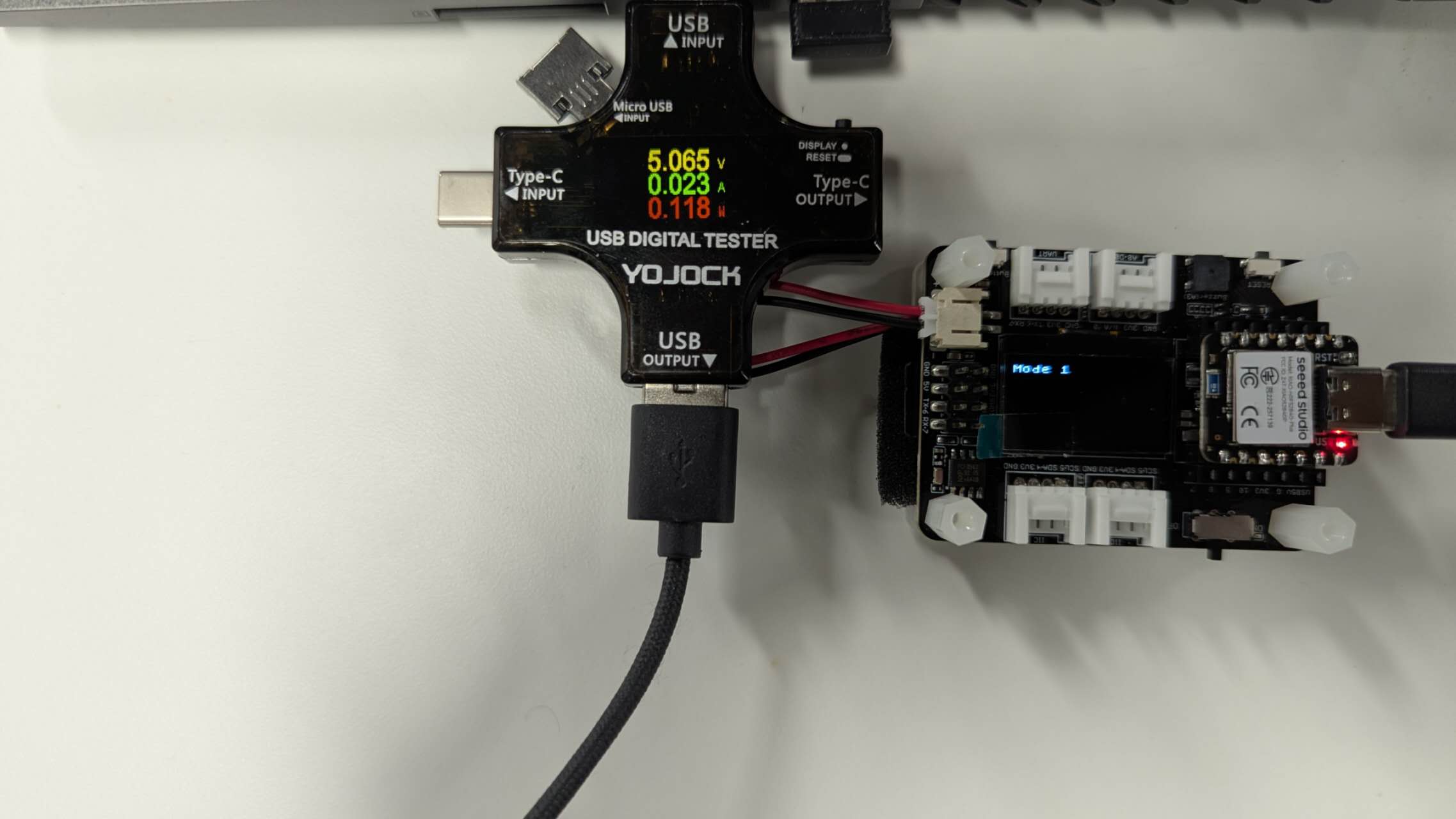
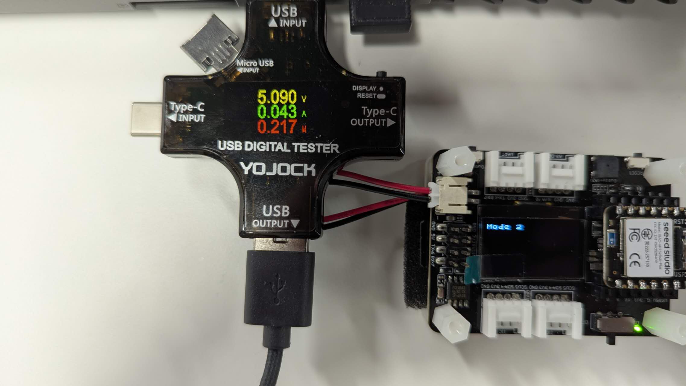
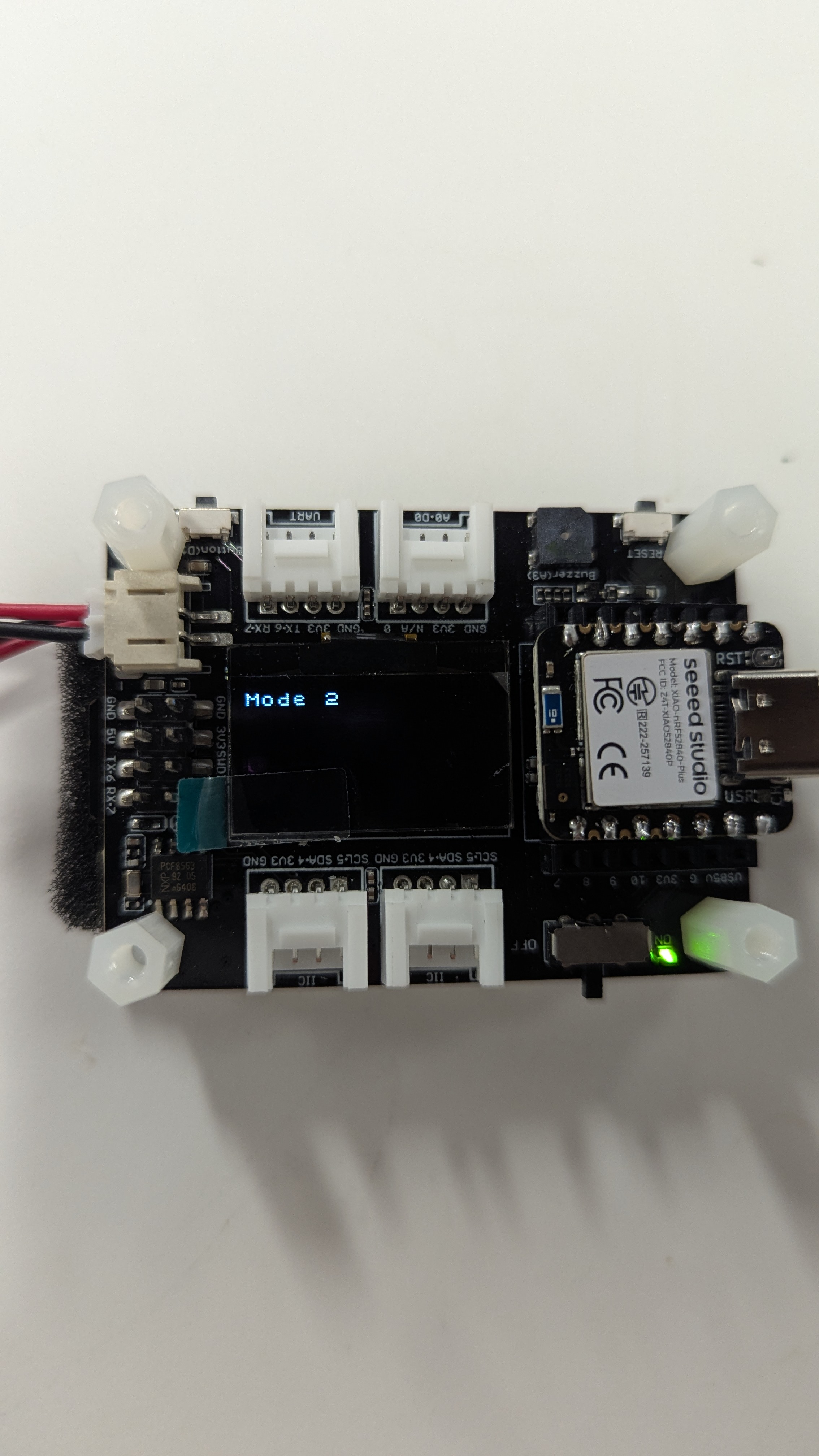
Since there are 2 mode, we will be controlling the switch of the 2 mode with low energy bluetooth (BLE). The current mode will be display on the OLED screen with Mode 1: display in serial monitor, Mode 2: store in SD card.
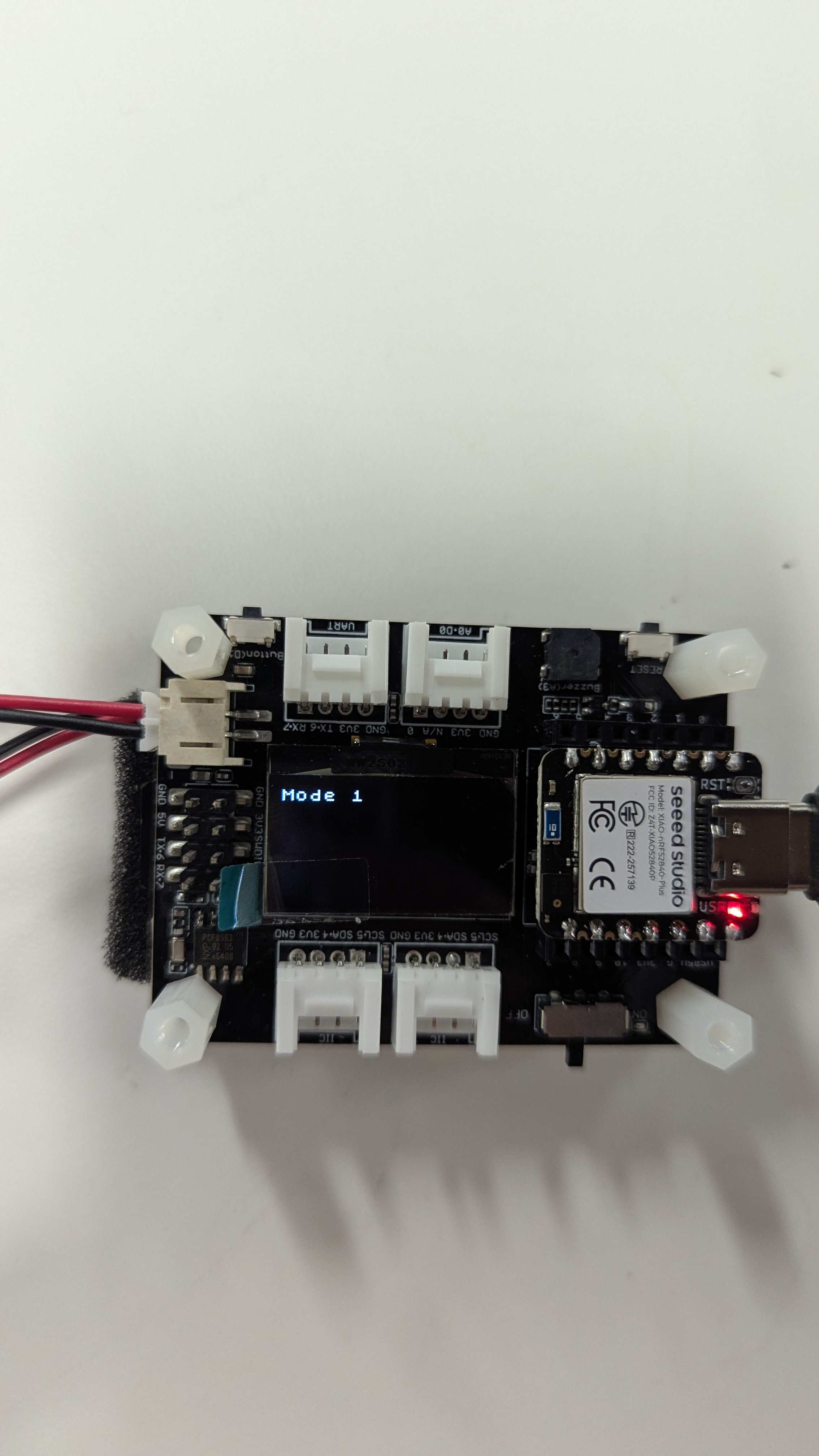
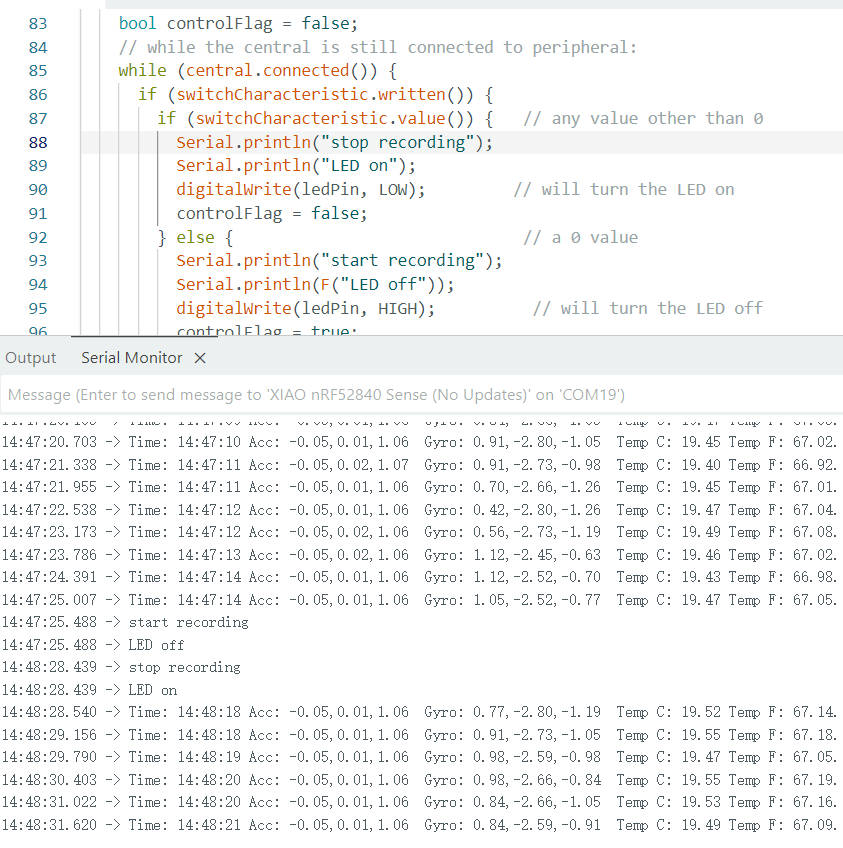
We can monitor the data being displayed on the serial monitor under Mode 1.
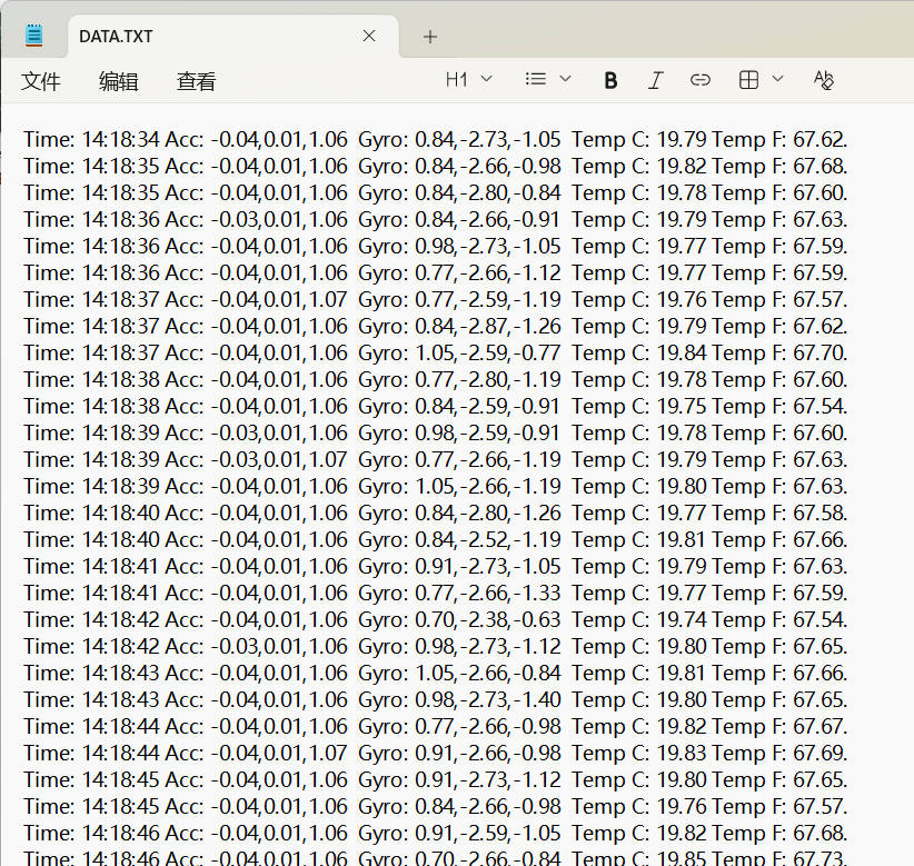
We can also record those data in SD card as a txt file under Mode 2.
We control the switch between the 2 mode using the bluetooth by using the nrf Connect app, which is avaliable on both Andriod and iOS.
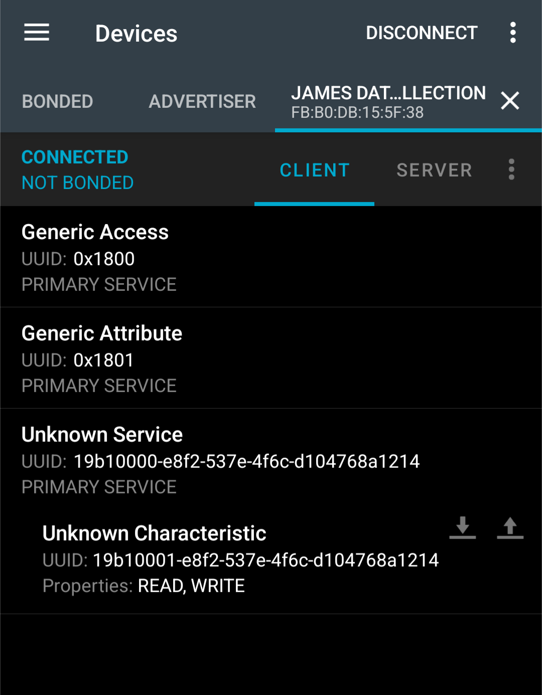
We can send a unsigned int 0 or 1 to control the mode switch.
In the following week, we also got a digital tester to see the power cosumption of those 2 different mode. I can observe that when writting information into the SD card in mode 2, the current will be spike suddenly, and when in mode 1, the current also bump up when output through serial port.